So during the last lot of works I needed a rev counter to
help me tune the carbs (on going issues I’ve been doing bits to for a while
now). I’ve always planned to fit one in the cab so as part of this I decided to
buy the Durite Tachometer now and install it at a later date, but rig it up to
work for the testing. The gauge comes with a back light, which is a clear
standard bulb. For my Defender, somewhere along the line I’ve decided to use
blue lights on all my dash, and during the install have been converting the
dash to blue, such as all the Carling switches and the clock – this has created
a bit of work for me but so far have been relatively easy. Carling switches are
a LED to replace (I will post the process for changing these up here at some
point), the clock was a simple push in bulb on the back.
The new gauge however is a sealed unit. A quick internet
searched came back with no results on how to change this bulb so I decided to
experiment (risky option, as the gauge was £50!). The results of this I’ve post for you
all to see.
This is what I started with, it has a clear bulb – so
slightly yellow light when on.
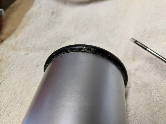
The worst part of this whole process was separating the
gauge housing. The metal bezel around the edge, at the back is pressed closed
around the internal plastic holder, external case, and glass. So the only way to get it open
was the pry this apart, so care was taken to carefully to pry it open, bit by
bit. Lengthy job, but worth doing slowly. Once the bezel is sufficiently bent,
it removes from the main body along with the glass and internal spacer. At this
point I’m pretty sure there is no more warranty with this product!
Once this is done there are two small nuts on the back
holding the internal mechanism in place, take these off and it comes out.
I rigged up a battery and some test leads to start testing
the bulb. It was a normal bulb inside that was getting full 12v, so a resistor
would be needed for the new LED.
Next was to identify which way the current was flowing, as
LEDs only work in one way. So I cut out the current bulb, leaving its tails in
place, and connected a few leads with a resistor and I had the answer.
Then I took off the circuit board to the back for access and
soldered in the new resistor.
Then the new LED.
Then connected the LED to the resistor, then refitted the
board back to the unit.
During the fitting of LED and resistor I used heat shrink
to guard the open connections to avoid shorts. The last section was a closed section so this
was wrapped in tape. Then the internals put back inside, bezel reflated.
I’m happy with the end result, the light is bright and as you
can see, blue. If you look at the back of the unit, it’s clear it has been
opened, but this part of it won’t be seen when its fitted into the dash, so all
good.


