Thursday, 9 January 2020

Head Lining Trim

 Just before Christmas (7+ weeks before), I treated the Defender to something I'd been looking forward to installing for some time. A new head-lining trim! The old version was removed some time ago now and even then was in poor condition as these things tend to be, especially when the previous owner fitted a roof rack by drilling into the roof, letting water in. Even back then when it was removed I knew what I wanted to fit - LaSalle Trim.

As it's been such a long time since then and now, that LaSalle have expanded their offerings to include different finishes. After consideration I purchased the full 110 CSW lining in the luxury finish RAL 9005 - Jet Black.

The product is sturdy, strong and has a fluffy finish. It's made from a Glass fibre product with the finish sprayed on - I've seen this finish before but can't think where. I like it a lot. The black I chose is very very black, it looks great, but is so dark it's difficult to take pictures of! Either way very impressed so far.


The first part of the install was to fit the front section, my Defender has a sun roof, and fortunately I had the foresight to save the original lining from this area so I could trace in the opening and cut out the new. This is probably the most well planned thing, that I've remember during this whole time!


The only way I was able to accurately marked the head lining was to fit the original on the finished side, mark with a pen, and drill the marks. This meant I was able to use the jig saw to cut from the other side without damaging the finish.


Next up I removed the lights I had temporally wired in.


And fitted the new section, which in this photos was held in place by the (scabby looking) mirror bracket.


There was a small bit of trimming to do, so it came down to enable this. At the same time (as time with my assistant was limited), I got the back section into place.


Temporally screwed into place, with hole for the lights and cable.


I then put back in place the front section, and drilled the centre section to allow the fitting of the light.


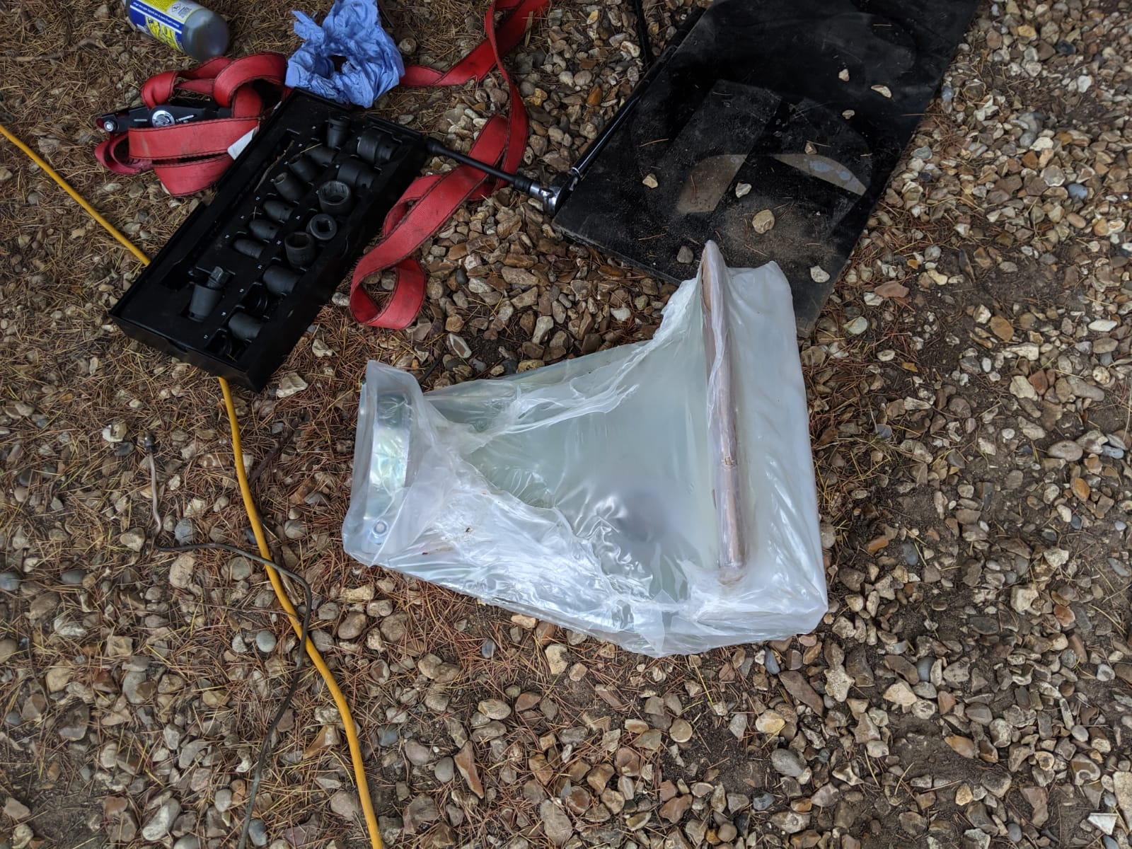
 Here we have all 3 sections in place, with door trims, final black fixtures, and lights fully mounted. Trim around the sunroof, and refitting the dog guard will be another post.


I'm really pleased with the result and the way it looks. Makes the Defender a much nice place to be. When I opened the packaging I was a little worried that the surface would be really hard to clean, but during all the works I've learnt that it's pretty easy. I found an airline or lint brush does a great job.

The process of install was fiddly, but the instructions were clear. Definitely worth having another pair of hands on the job!

Up next will be the side trims - recover and fit!

Thursday, 12 September 2019

Slick Shift Install


Today I’ve done something I’ve wanted to do for a long time. Install a Syncro Gearboxes Slick Shift. The reasons I’ve not been able to do this before is they did not make a slick shift to suit the LT85 which I have in my Defender. But recently they released a new version!


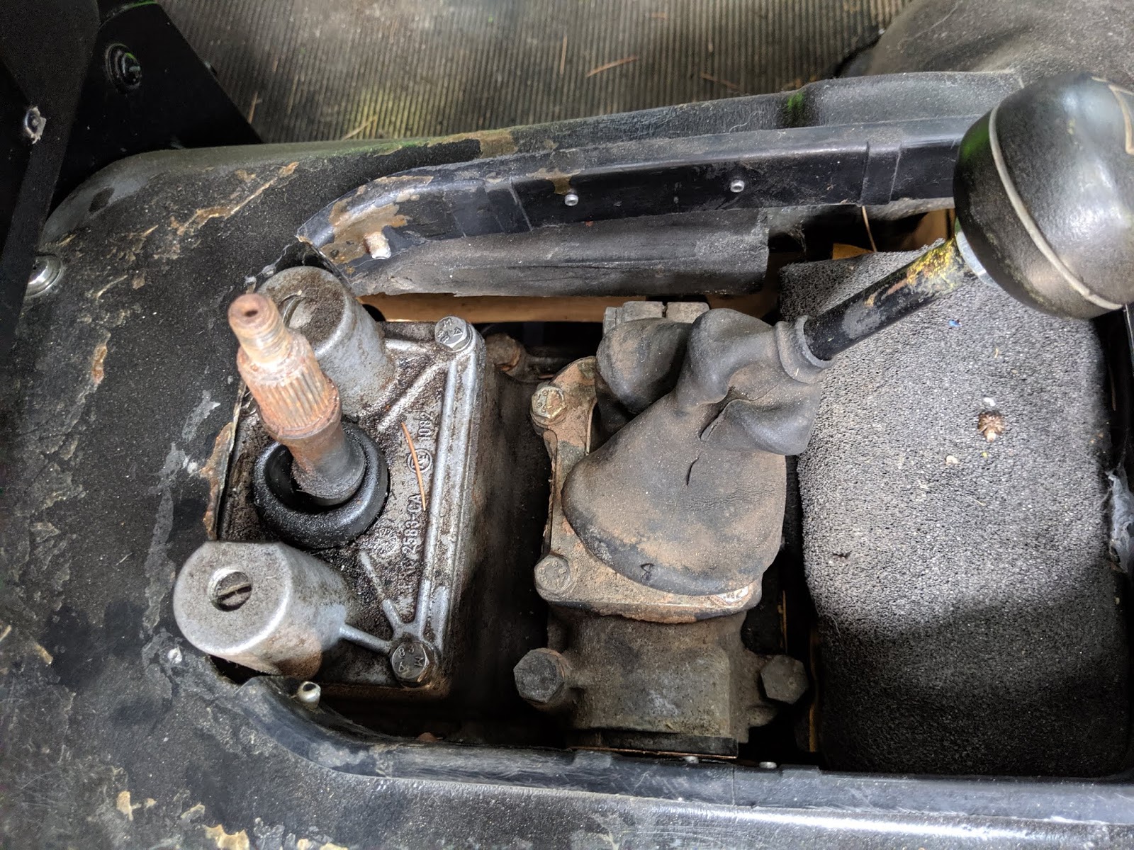
I won’t go into too much detail on this install as the YouTube instructions they have are very good. Y first task however is not normal. And that is to cut the transmission tunnel back further to allow access. Normally this would not be required, but I have and R380 tunnel tube in place, so that later I can fit the Exmoor moulded matting system to the front – again LT85 not being very popular meant there is a matting system for this type of gear box / vehicle combination. As you can see in the pictures I can’t access the top of the shift box.


So out with the Dremel. A tool a seldom use as it’s pretty useless, and surprisingly very poor quality – it’s already whining and splitting in two after very little use. However, for this job it worked well. Its not the neatest of jobs, but when I reshape the top of the tunnel, I’ll take care of this.


Removed the old parts ready for cleaning.


These screws where a pain – as suggested in the video. I got a bit of heat into them and they eventually came out.


All nicely fitted.


Although between the last two photos was a lot of messing around. Once fitted – with grease and silicone sealant, I couldn’t get reverse. I tried this a few time, cleaning and refitting grease and silicone multiple times – very messy! In the end I worked out that if I fitting all parts, lightly tightened the bolts that hold it down, and then select reverse, and fully tightened, this solved the issue and it worked find.

I think this issue is just a by-product of my old worn box, and a difficult reverse. Either way, it’s all done now and a great improvement on gear changes!

Sankey Camping Trailer project.....


In a slight deviation from the Defender project I’ve started a camping trailer project too! Why finish one project when I can have multiple on the go! I’ve always planned on doing this, but was planning to do so after the Defender was complete. But things have switched up a bit as parts of the build have come available cheap on the net, and the desire to want to use it now that investment has started.

I was wanting to recreate the classic back of a Defender on a trailer, so wanted to have something which would have similar wheel base / size to a Defender.  So, it started off that I was going to use a ¾ ton Sankey Trailer as this fits the bill, which I got fairly early on as I could use it as a normal trailer until the time came. But the more I used it, the more I got to thinking how I would miss it once it was converted. And so the plan changed again, keep the Sankey, and look for a second trailer…..

Shortly in to 2019 and I spotted a frame trailer, ex-military used for transporting water tankers, Nato hitch, 2t capacity, and a lot cheaper than the Sankey was! And same wheel track /size. So I thought that’s that done, brought it and got it home.
I then started thinking about how suitable the new trailer would be for the purpose of camping trailer. A few of the points which raised concern were:

1.       The new trailer has a much higher load rating
2.       It has less suspension travel
3.       And it’s frame / overall height is lower

The issues with these points are that fact that as a camping trailer it would never be loaded close to its rated load capacity, which would mean the suspension wouldn’t be compressed, and operating fully (if at all, unloaded it bounced down the road when I collected!). If the suspension wasn’t working, and it bounced all the time, it would shake everything up and make it worse to use off road, or at all.

The lack of suspension movement would limit its stability off road, and the height of it would mean the Defender body would need to be stuck on large spacers to ensure the trailer body line matched that of my Defender’s body line, and possibly due to the hitch height may be at a steep angle.

So, a new plan was needed. And what you see below is the start of this new plan. The idea is that I will take part of the Sankey – tub, rear cross-member and transfer to the water trailer. This will give me a Sankey-ish trailer with a higher load rating that I can use for transporting stuff and waste.

Then mount the Defender body onto the Sankey frame and build from there - as originally planned.

So the start, a perfectly good 3/4 t Sankey.


And a perfectly good water bowser trailer. With the support legs removed.


Off with the Sankey tub


Then off with the cross member and lights within.


Then removed the wheel arches, and welded on some extensions on the front and braces to the centre of the water bower trailer to support the tub.


Cut the back-marker triangle off. A welded on some plates to allow the trailer frame and Sankey cross member to line up.


Weld the Sankey cross member on.


Popped the body on and bolted it up.


There is still some work to do to finish this but it works for now. Jobs to complete for work trailer: wire electrics, replace jockey wheel, and re-fit lashing points inside.

I then moved on to the camping trailer. I offered up the body and worked out what needed to move. There were two eyelets on the front that had to be cut off, and the brake reservoir needs to be relocated. There is enough room in the back to mount the new cross member, but the front A frame needs to be extended by about 400mm to give clearance of swing from the tow vehicle. The body also needs to be raised up to get the line correct. 

Here it is with the body sat on the trailer without the packing to achieve height.


I then took the body off and began work on the chassis extension. I started by cleaning the area to be cut, and marking it with pen. I opted for this point as this is the max width that will fit under the front part of the Defender tub, and it also means that the brake reservoir would be moved also - which needed to happen and I don;t ave to mess around with the brake linkage, just extend the brake line.


Then on to the point of no return: cutting.


I then offered up the two new extension pieces, clamped them in place and tack welded.


The end section of the trailer was then stripped of all parts, and clamped, followed by some tack welds.


The whole thing was then fully welded after some tweaking to make sure everything is where it’s meant to be.


I remounted all the front end kit (jockey wheel / tow Point), then gave it a quick spray to stop it rusting.


Once I’ve mounted the body fully I’m come back and weld some plates top and bottom to stiffen is up as has been done on the rest of the trailer.

The next task was to mount the rails the tub would sit on. Firstly I test fitted the body on some loose bits of metal. I started with 75mm, after measuring the tub and it’s recesses. It lined up fine.


The next task was to weld in the bars that the will tub sit on.


I found some red oxide so gave everything a coat for temp rust prevention while it’s being worked on. Mounted the rubber pads to the bars to stop vibration. Normally these are mounted to the underside of the tub, but I opted for this way.


Stuck the body on to make sure I was still happy.


Which I am, looking good so far. Next is the front tub bolting points, and the rear cross member, and that should be the body mounted. But that is all for today.


Tuesday, 6 August 2019

Rear Axle Air Locker Install


As noted in the prior post, I opted to complete the rear locking diff install at the same time as I did the front. Jumping between the two when parts / time permits. I completed the front relatively quickly, along with compressor and other bits, as these were comparatively easy jobs. The rear diff was more involved, and as such I’ve only just completed it. As with all things in life, it’s easy when you know how, unfortunately I don’t have a clue!
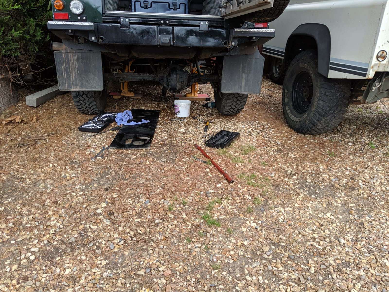
You may note that this diff is being installed into an axle that is not fitted to the Defender, which having just finished it I’m glad of as this would have been a complete nightmare to do if fitted!
The reason the axle is off is because this is another axle, new to me. I brought this as I noted an error in my welding of the brackets to the other Sailsbury, which meant the axle did not sit square with the chassis. Resulting in a crabbing vehicle. Making it more of a challenge to drive, and near impossible to align all the wheels, again adding to the drive-ability. So this was brought, cleaned and painted, stored ready for fitment. The idea is I’ll pull everything off the old(ish) axle from the stub axle and stick on the newer axle which is still relatively new.
So here it is, the new axle ready to have it’s transplant. Unfortunately, it’s taken a bit of beating in my garage so the paint needs a refresh.


And here is the shiny new ARB Air Locker with the install kit.


There are a few special tools that the manual, both LR and ARB, advise are needed. And not only are these hard to get but also expensive when you can find them. To combat this, I’ve opted to make my own. These are diff spreader, pinion flange brace, DTI holder, and precision height gauge.
First up I made the diff spreader. The LR part for this is really hard to find, the ARB version is over £300. The idea with this part is that it pulls the diff apart by 0.5mm to ease the install of the diff into the case.
This was made up of a steel plate either side to act as the spreading structure.


Made up with brackets to support threaded rod to spread the diff. The plates were drilled to allow citing bolts – these bolts do not take the horizontal load but stop the plates from rising up under load. Lugs were welded into the bottom to fit into the spreading holes within the diff housing.


I left the bolts used to create the lugs long and used a welded nut to mount them, this enabled a bit of adjustability. Once the correct depth was determined these were welded into place, and the frame stamped to indicate direction of use.


This is the frame with all parts fitted and ready to use. I went a bit overboard on the treaded rod size, but it make it easy to spread the diff.


The first job was to measure the existing backlash for future records.


Then the diff was spread (spreader working very well), and diff removed.


Now the new diff was assembled and ready to fit, I started making the next tool, Pinion flange brace. This was just a section of angle with bolts welded into it to hold the pinion flange while the nut was undone.


Once that was made the pinion was removed, and the old bearing  race removed also. Allowing the new bearing to be installed.


The pinion was then reinstalled using the correct shim value. Which was obtained by using the last two special tools. Precision height gauge, which for a Salisbury is 30.93mm. I had this made by a small engineering firm as they could get the required tolerance. The other was the DTI holder.


This process involved using a flat plate and the gauge block to get zero and then measuring the bearing race cups from a DTI that mounted to the pinion gear, splitting the difference and determining shim value. This took a lot of messing around, so I ground down the older bearing race so that the new race did not need to be fitted and removed multiple times, as this is a very tight fit. The ground down race dropped in and out with issue.

Pinion now in.


Then the pinion was covered over with cloth, and the new hole in the diff case for the airline was made.


The shim and backlash calculations were made as advised in the ARB instructions and the diff fitted. Airline bent into place.


The last few steps above made the fitting of the diff sound quick and easy, but the reality was far from it, there was a long time of fitting, removing, working out shims that went into the above. Coupled with other jobs, limited time on this, the whole process ran into months. I consulted forums and got good advice, such as only use genuine Timken bearings. And retracing the process from the start revealed a small mistake that caused issues later on. But nether the less it’s in.
Then I repainted it to make good to the damage that occurred during this time, and added the final fittings ready to be mounted.


Next step was to start the swap, firstly by removing the old(er) axle.


Bit of a crappy job, rolling on the floor, undoing rusty nuts under a propped vehicle. But went well with the exception of the self-levelling unit, which spilt in two and poured oil all over me. Seems the internal bar that goes through the centre has damaged thread. Another small issue was that a brake pipe fitting ceased and twisted the brake line, so this will need to be re-made.


Then I started to remove the components from the old axle.


And on to the new. At this point I also fitted the Ashcroft half shafts and drive flanges.


And repeat for the other side.


A rolling axle!


The axle was then rolled under the vehicle, springs and shocks connected. I also bolted into place the new trailing arms. I decided to switch the X-arms as these look to be a good products.


Once both arms were fitted I moved on to the a frame, minus the self leveller. Looking around on the net, the general consensus is to remove the self leveller permanent once it's failed and fit stiffer springs, or the 130 spring assisters. The springs I brought were intermediates so I'll run with these and either try and repair and fit the self leveller, or fit spring helpers if needed.  The new brake line was made up and both sides fitted.


I also had some more goodies to fit. New diff slider, and an X-Deflect anti roll bar system. I did consider the ARB / D44 weld on pan, but thought this was a bit extreme for what I intend the Defender to be sued for, and the sliders are a good compromise. Similarly the X-Deflect will hopefully make the Defender a lot nicer to drive on the road, lifted with bigger tyre can make it a hand full sometimes.


Diff slider in.


And then the X-deflect in.


Job done! This bit has been in the making for some time, so it’s good to have it done. Now… what to do next?